


Seeing that the previous two rounds of audio quality testing failed to find any significant differences in performance based on capacitor type, Allion decided to investigate additional testing strategies. After some research, we found that some audio magazines mention a ‘whisper’ or ‘breathing’ sound, which inspired this third round of testing.
In audio quality testing, most researchers use a maximum signal volume of -20 dBFS or -60 dBFS, and a sampling frequency of 1 KHz. However, for this third round of testing, Allion used the settings outlined below:
Audio Quality Testing – Test Item Matrix
1. Level Sweep vs Frequency
2. -40 dBFS THD+n vs Frequency
3. Noise Recording
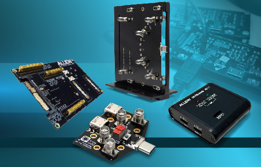
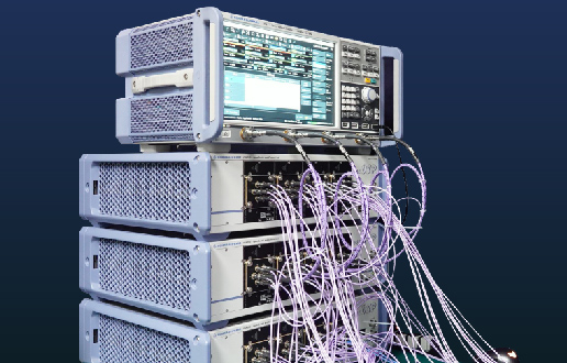
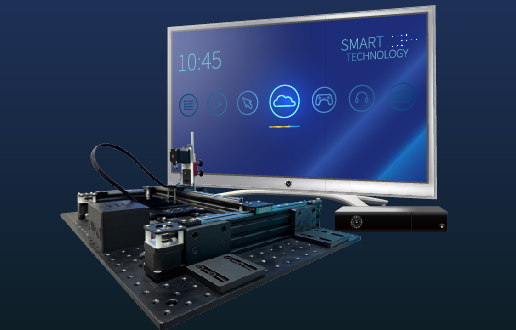
For this round of testing, we used test instrument Audio Precision APx585 and signal generator SYS-2722 to generate the signal source directly.

Figure 1 – Audio Precision SYS-2722 & APx585 Test Instruments

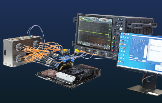
Figure 2 – Connection1 (standard) and Connection2 (new test setup)
1. Level Sweep vs Frequency
We chose to input signals at various frequencies (10 Hz, 20 Hz, 100 Hz, 500 Hz, 1 KHz, 5 KHz, 10 KHz, 20 KHz, 40 KHz). For the level sweep, we adjusted the input signal to the DUT between 0 dBFS and -120 dBFS. The graphs below show the DUT output results with both capacitors types.
Level Sweep vs Frequency – Electrolytic Capacitors

Level Sweep vs Frequency – Solid Capacitors

At the 40 KHz input frequency, these two capacitor types showed slightly different results. As shown in the graph below, the minimum signal output was -90 dB for the electrolytic capacitors (red line) while the minimum signal output was -100 dB for the solid capacitors (blue line). This 10 dB gap means that the solid capacitors performed slightly better at the 40 KHz frequency.
Level Sweep vs Frequency – Electrolytic vs Solid Capacitors @ 40 KHz

2. THD+n vs Frequency
We decided to use a -40 dBFS input signal to simulate the ‘whisper’ or ‘breathing’ sound mentioned in the introduction, despite the fact that this signal is rarely used in audio quality testing. Using both -40 dBFS and -60 dBFS input signals for comparison, we observed the resultant output signal distortion across the full frequency range.
With a -60 dBFS input signal, we observed a 0.5 dB difference between these two capacitor types.
THD+n vs Frequency with -60 dBFS Input Signal

With a -40 dBFS input signal, the solid capacitor had less distortion (-1 dB) than the electrolytic capacitor. This was twice the level of distortion at -60 dBFS, which is a relatively large increase.
THD+n vs Frequency with -40 dBFS Input Signal

3. Noise Recording
Every audible sound affects the listening experience, including noise from the audio device itself. For our final test, we monitored the output electrical potential when powering the system on/off.
The two capacitors showed obvious differences when the system was powered up and down. The electrolytic capacitor type had higher electric potential during both power on and power off. The pop sound curve (shown below) reflects the change in electric potential that we observed.
Electrolytic Capacitor – Pop Sound Curve

In comparison, the solid capacitor had lower electric potential than the electrolytic capacitor. The pop sound curve was also different from the electric potential curve. The highest surge points for these two capacitors were very similar, but during power on, the solid capacitor had 5 dB less ‘pop’ than the electrolytic capacitor.
Solid Capacitor – Pop Sound Curve

Conclusion
In this third round of testing, Allion used customized test methods to compare the audio quality performance of electrolytic and solid capacitors. From our test results, we found that solid capacitors showed better performance.
In the circuit model shown below, A and B are the audio output connections. In this circuit, the Low Equivalent Series Resistance (ESR) capacitors are imperative for high power supply efficiency.

Although solid capacitors have low ESR, this did not make much difference in our audio testing. Neither did the fact that the solid capacitors (2 W) were more powerful than the electrolytic capacitors (0.5 W). During testing, we also worried that current leakage might affect audio quality; but we did not observe this problem in our test results.
The capacity versus frequency curves for both types of capacitor are provided in the figures below. The electrolytic capacitors show a dramatic capacity change in high frequencies. In other words, their electrical capacity goes down significantly at high frequencies. In comparison, solid capacitors have a stable electrical capacity at high frequencies, which is a better result.
Electrolytic Capacitance vs Audio Frequency Curve

Solid Capacitance vs Audio Frequency Curve

Looking back at all three rounds of testing, we used various methods to compare the audio quality performance of electrolytic and solid capacitors. In the first round, we used the standard audio quality test criteria. We applied a -20 dBFS signal, within the full audible frequency range (20 Hz – 20 KHz) and tested the most common audio sampling rates (44 KHz and 48 KHz); however, the test results for the electrolytic and solid capacitors remained very similar.
In the second round of testing, we used a digital audio source file with a sampling rate of 192 KHz. This source file could (theoretically) reach an audio frequency of 90 KHz, but the test instrument (Audio Precision SYS-2722) restricted us to an upper limit of 80 KHz. Based on this logic, we created a new sweep audio file that could reach an audio frequency of 80 KHz and set the bandwidth to 80 KHz. Despite the expanded audio and sampling frequency ranges, there seemed to be no difference in audio quality between the two capacitor types.
The third round of testing used three advanced test functions for capacitor type differentiation:

From these test results, we have demonstrated that solid capacitors have slightly better audio performance than electrolytic capacitors at both high and low frequencies. The audio industry usually relies on subjective human judgment to assess audio quality performance. However, in our testing, we used objective techniques to collect measurement data and evaluate the results.
In the future, we promise to continue these audio tests to provide more effective test methods to our clients. If you have any questions or test requirements, please contact us: service@allion.com
Related Articles: