


Allion Labs
The Mobile Industry Processor Interface (MIPI) is a set of regulations defined by the MIPI Alliance for the design of processors for various mobile devices (smartphones, tablets, laptops, mixed devices, etc.). As technologies such as 5G, AI, and IoT mature, there is greater demand for related processors and devices, in which MIPI regulations play an important role.
There are six types of interfaces in MIPI regulations, in which the type of Multimedia in MIPI regulations is mainly divided into three layers, as shown in the figure below:
- Application Layer
- Protocol Layer
- PHY Layer
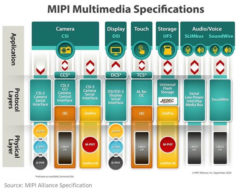
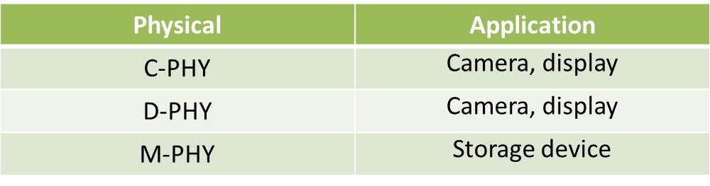
The main applications for MIPI can be divided into three types: Camera (CSI), Display (DSI), and Storage (UFS).
Just like most of the technical interfaces, the MIPI Alliance has developed a standardized testing document to define and specify the testing conditions, methods, and items. The MIPI testing files are called the “CTS/Conformance Test Suit”, which can effectively reduce problems related to image latency, noise/blur/distortion on images and photos, etc., if the Conformance Test indicates “Pass”.
Unlike general certification tests, it allows manufacturers to perform their own conformance tests with reference to the testing document guidelines, without having to go through such tests in a third-party association’s accredited certification laboratory. For conducting such tests, proper testing equipment and environment should be made available beforehand; however, according to our many years of testing experience, this is not the biggest problem that most manufacturers may encounter. The main reason is that they lack sufficient testing experience. Since MIPI is often applied to the interior part of a mobile device, the testing measurements should be conducted by means of making direct connections through soldering or probing. As a result, the testing measurements are more difficult to be carried out, if compared to the methods for common external interfaces such as USB or HDMI.
Here, by taking the commonly seen D-PHY/C-PHY as an example, Allion Labs will share our experience regarding some frequent problems in product testing.
Learn more about MIPI D-PHY
MIPI D-PHY is a signal transmission mode that combines high speed with low power consumption. It is primarily used in Camera (CSI) and Display (DSI).
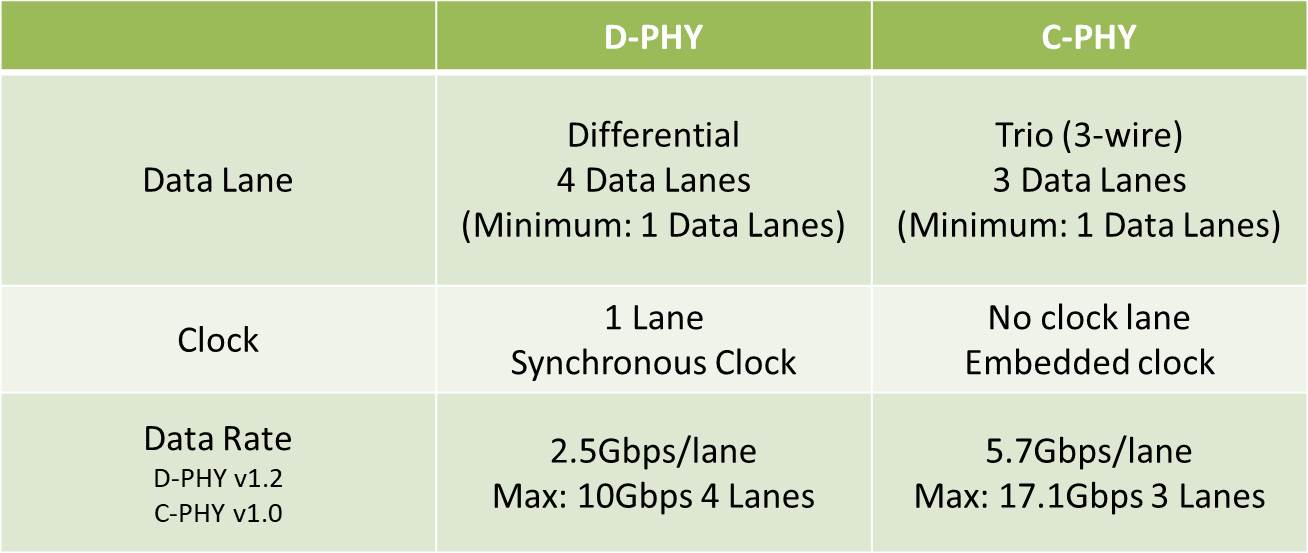
The signal combines 1 pair of Clock differential signals as well as 1 to 4 pairs of Data differential signals. It also supports the switching between HS mode (High Speed) and LP mode (Low Power).
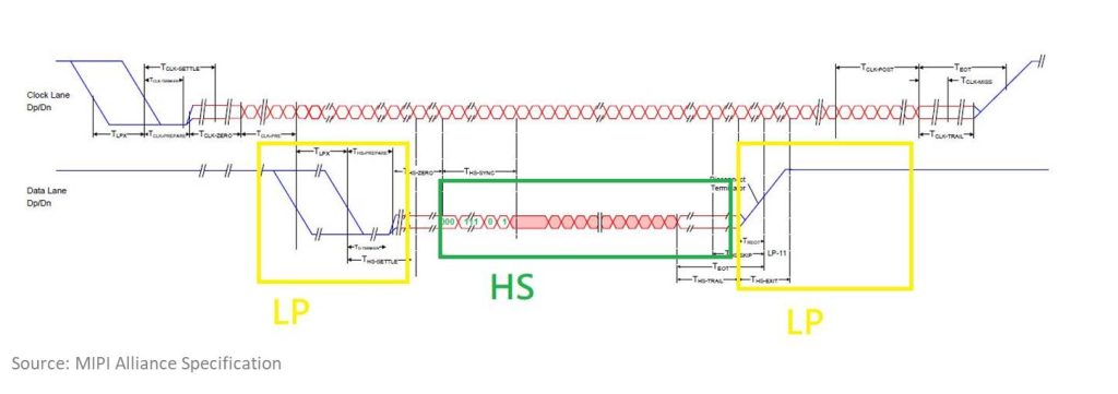
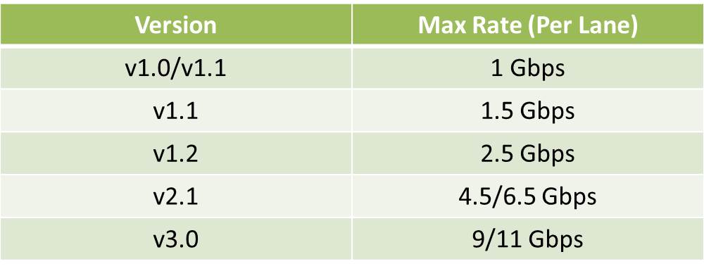
HS mode: Low voltage transmission, highest data transmission speed at 1Gpbs~9Gbps per lane.
Requirements and Methods for Transmitter (TX) Testing
Since the lens and video display interfaces on smartphones, tablets, and automobiles are already finished products, signal testing measurements can be conducted only through direct connections such as soldering or probing, as mentioned earlier.
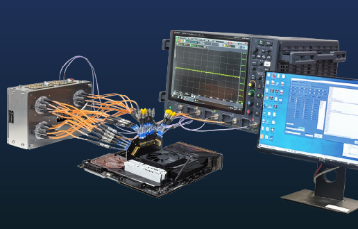
The figure below indicates a connection diagram of the test environment:
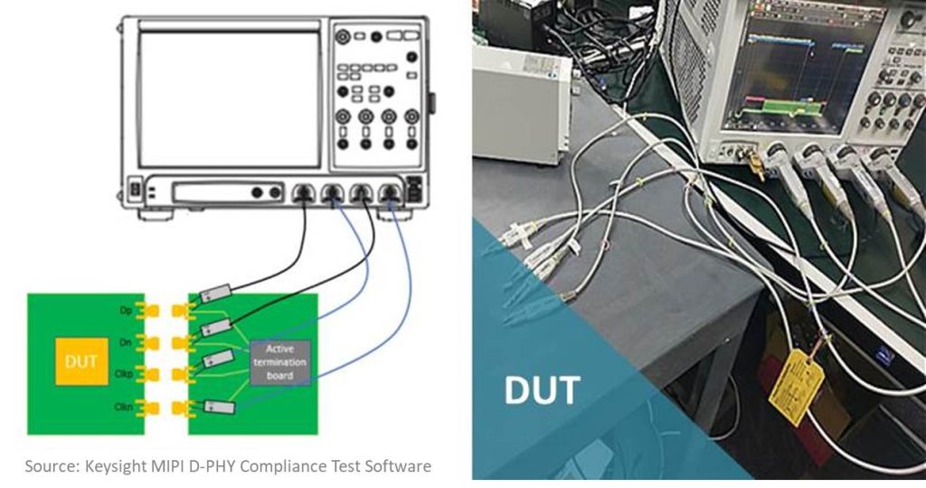
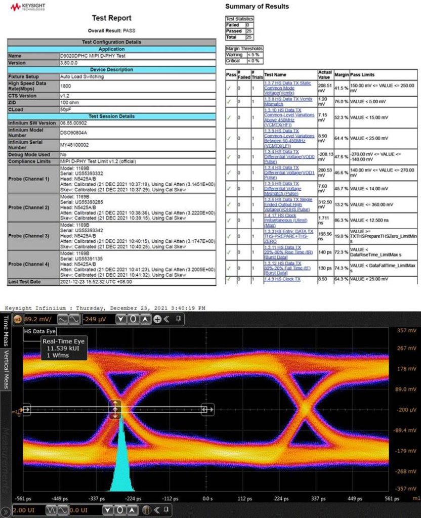
For our testing equipment, we use Keysight D9020DPHC and compatible testing software, to conduct comprehensive tests based on the specifications under MIPI D-PHY v2.1 in Section 9 and C-PHY CTS V2.1 in Section 1.
Main Test Items
- High-Speed Data/Clock TX
- Low Power Data/Clock TX
- Data/Clock Transmitter(HS Entry、HS Exit)
- High-Speed Data-Clock Timing
Learn more about MIPI C-PHY
Like D-PHY, the signal transmission mode combines high speed with low power consumption, which is applied to CSI and DSI.
The main differences between the two are listed as follows:
Requirements and Methods for Transmitter (TX) Tests
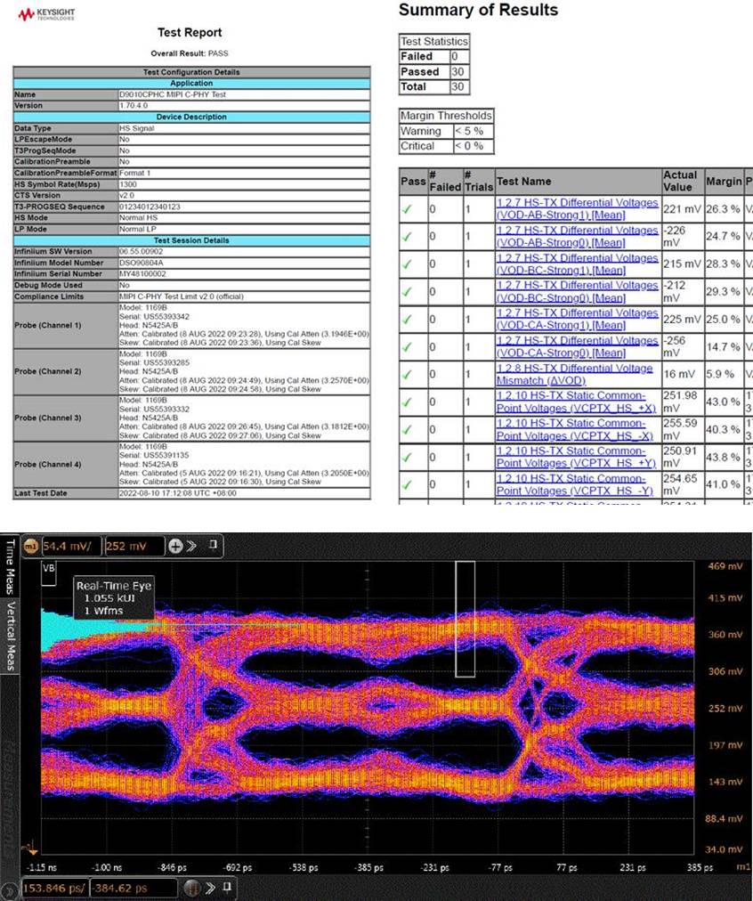
For our testing equipment, we use the Keysight D9010CPHC MIPI C-PHY Compliance Test Software, to conduct comprehensive tests for the specifications under MIPI C-PHY v1.2 in Section 9 and C-PHY CTS v1.1 in Section 1.
Main Test Items
- High-Speed Transmitter (HS-TX) Electrical Tests
- Global Timing Tests (T3-Prepare, HS Exit)
 The foregoing diagram indicates and captures the signals from different modes
Case Study
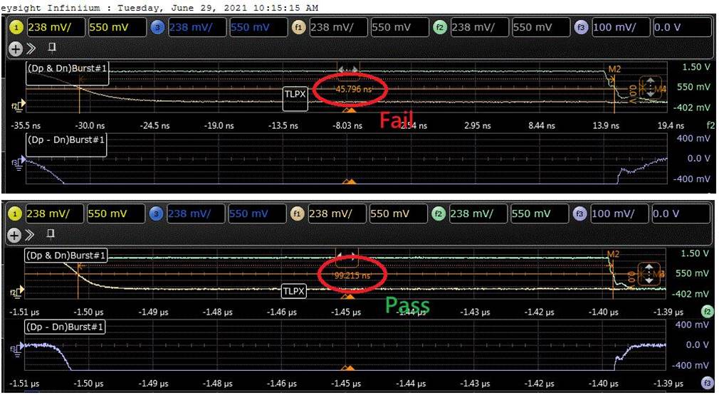
1. Location Affects Test Quality
The primary regulations of MIPI D-PHY/C-PHY TX are for testing the output end of the chips.
If the test points are located too far away, it might affect signal attenuation; furthermore, when the driver capacity is insufficient, it will lead to insufficient rise/fall climbing capacities, resulting in overspecification and poorer quality signals.
D-PHY
C-PHY
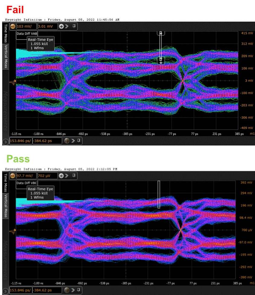
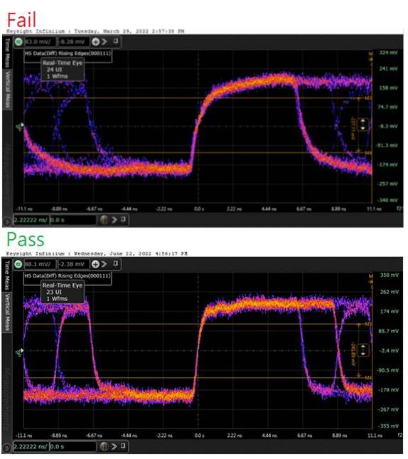
2. Errors in Adjusting the Setting of Chip Timing Parameters May Result in Test Failures
Due to the problems in the setting of chip timing parameters, Data/Clock Transmitter (HS Entry, HS Exit) timing fails. Allion Labs suggests that chip manufacturers should provide adjustment parameters to adjust the “timing skew fail”.
From the diagram below, we can see that over specification will occur when the parameter falls below 50; on the contrary, the data result indicates “Pass” if the value is above 50.
Allion Labs has enacted comprehensive solutions, to help customers conduct the testing measurements of parameters in accordance with MIPI standards, to ensure that our clients’ devices demonstrate excellent performance. Allion Labs also boasts relevant devices such as DDR, UFS, Ethernet, etc. that can provide various signal integrity testing capabilities. If you have any testing needs, please contact us via our contact form here at any time.