


The PC industry is becoming saturated, so many motherboard companies are looking for new markets and high-quality audio market has become their new target. In the high-quality audio device market, new products gradually spread to consumers and related components and accessories appear.
According to experts, a good audio device deliver a “beautiful”, “clean” and “deep” sound. Audiophiles often associate this sound with the use of electrolytic capacitors. For this series of technical articles, Allion explores the subject in greater depth. We now ask the question – Is it possible to define high-quality audio with special tests?
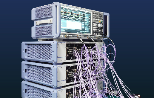
Allion used various instruments to collect audio measurements, compare capacitor products, and detect differences between audio tests.
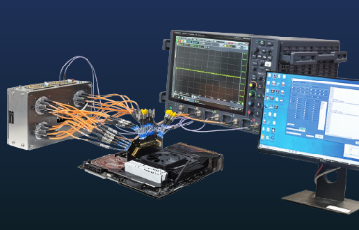
Test Setup
|
Instrument |
Audio Precision SYS-2722 & APx585 |
|
DUT |
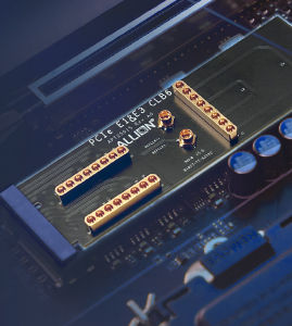
100 µF / 6.3 V Electrolytic and Solid Capacitors |
|
Test Bed |
ASUS Z97-K Motherboard |

Test Purpose
Apply different electrolytic and solid capacitors on the same high-quality motherboard to explore the impact on overall audio quality.
Test Items
1. Full Scale Output Voltage
This test item measures maximum output voltage. If the distortion exceeds 1% of the original signal, the sound waves are usually truncated, which makes for a poor listening experience.
Because this test item is designed to measure perceived distortion, we excluded frequencies that the human ear cannot detect. To achieve this result, low-pass and high-pass filters were set to 10 Hz and 22 KHz, respectively. We used a criteria of THD + N <= 1% (see test item 2) to find the maximum output voltage. This result established a reference voltage that was used in subsequent tests.
2. Total Harmonic Distortion+ Noise Frequency
In the real world, devices produce imperfect (nonlinear) sound by introducing distortion, usually by adding harmonics after conversion. Harmonic distortion is easy to identify because it always occurs at whole integer multiples of the original signal frequency. For example, an audio frequency of 1 KHz will include harmonic distortions at 2 KHz (2nd harmonic), 3 KHz (3rd harmonic), 4 KHz (4th harmonic) and so on. Total Harmonic Distortion (THD) adds up all that extraneous harmonic energy into a single value to provide a measure of audio signal nonlinearity.
3. Dynamic Range
Dynamic range is the ratio of maximum original signal strength to the minimum distortion or noise. For a 16-bit digital signal, the ideal maximum value is -96 dB.
This test item also measured Signal-to-Noise Ratio (SNR). Dynamic range and SNR are similar but slightly different in terms of the test method. The audio industry is accustomed to input -60 dBFS for weak signals because the input signal is close to actual usage. Under normal conditions, such weak signals are equivalent to noise.
In addition, the audio industry generally applies an additional "A-weighted" filter curve that removes high frequency and low frequency signals beyond the range of human hearing. This curve also accounts for the sensitivity of the human ear to various frequencies. Using this filter, we focused on the audible frequency range.
4. Noise Level During System Activity
Sources of noise include unwanted internal sounds originating within the audio product itself and signal interference from external sources. SNR is a poor measure of audio quality since it uses an arbitrary reference level for noise. Dynamic range is a better measure, as it reflects real-world performance.
Using the same test method to monitor the system is convenient and efficient. We can examine how high the output voltage is and get the relative reference dB value when the system is under a certain condition. This method can be applied to many different situations, such as monitoring if there are sounds during system reboot.
5. Frequency Response
Following the AES17 standard, we applied a -20 dBFS signal, based on the full-frequency range (20 Hz-20 KHz), and then observed the output voltage at each frequency. The best way to evaluate audio signal non-linearity is to observe performance stability, power attenuation, and signal jitter. Faulty components or circuit design can affect sound quality.
6. Crosstalk vs Frequency
Crosstalk is an electromagnetic disturbance that results in one signal interfering with a second signal in a different circuit or channel. Crosstalk is a common problem with analog signals. If crosstalk occurs between two stereo signals transmitting different messages, it will degrade the audio quality by interfering with the stereo transmission, soundstage, and positioning.
For our crosstalk test, we prepared two signals:
- 20 dB full-range signal with sound in the left channel
- Stereo signal with no sound in the right channel
Since we copy the mono signal to both channels, we used a stereo signal with a silent right channel. We also prepared an opposite signal for testing purposes.
7. Inter-channel Phase Delay
Ideally, audio systems should maintain signal consistency and phase in each channel. Phase measurement calculates a ratio between the input signal phase to the output signal phase. The difference in phase between these two signals is a reflection of the electrical characteristics of the device under test.
In this case, we wanted to explore whether the input/output signals will synchronize with different channel delay situations. According to the test instrument settings, we used a -6 dBFS signal to comprehensively examine the phase delay.
Test Results
1. Full Scale Output Voltage based on Sampling Frequency

This product meets the specification, as the distortion rate is less than 1% for a one Vrms output. In fact, if we input a zero dBFS signal and turn up the volume to maximum, we only get 0.012% distortion (THD+N Ratio). Moreover, sound wave differences cannot be detected when the distortion rate is under 0.2%. The sampling frequency accuracy is also well under 0.02%. In summary, the two capacitors under test performed well, yielding nearly identical test results.
2. Total Harmonic Distortion (THD) + Noise (N) vs Frequency

Electrolytic capacitors with 48K audio

Solid capacitors with 48K audio


Electrolytic capacitors with 44K audio

Solid capacitors with 44K audio

This product meets the specification, since the Total Harmonic Distortion plus Noise (THD+N) is less than -80 dBFS within the audible frequency range (20 Hz-20 KHz).
We also did not encounter any resampling errors, so the two capacitors exhibited very similar performance on this test.
3. Dynamic Range (A-Weighting)

This product meets the specifications since the readings were less than -90 dB after applying the A-weighted filter curve. The difference in test result values for the two capacitors was also less than 1 dB, with no difference in the jitter readings.
4. Noise Level During System Activity (A-Weighted)

This product meets the specifications since the readings were less than -90 dB after applying the A-weighted filter curve. The difference in test result values for the two capacitors was also less than 1 dB, with not much difference in the jitter readings.
5.Frequency Response

Electrolytic capacitors with 48K audio

Solid capacitors with 48K audio


Electrolytic capacitors with 44K audio

Solid capacitors with 44K audio

This product meets the specification since the attenuation results in the low band were less than 3 dB and less than 1 dB in the high band. The ripple of the passband was also less than ±0.25 dB. Therefore, there were no clear differences for this test.
6. Crosstalk vs Frequency

Electrolytic capacitors with 48K audio

Solid capacitors with 48K audio


Electrolytic capacitors with 44K audio

Solid capacitors with 44K audio

This product meets the specification since the two-channel leakage power was less than -60 dBFS within the specified frequency range (20 Hz-15 KHz). There was no significant difference between the capacitors.
7. Inter-channel Phase Delay

Electrolytic capacitors with 48K audio

Solid capacitors with 48K audio


Electrolytic capacitors with 44K audio

Solid capacitors with 44K audio

The results show that this product meets the specification since the difference in the two-channel phase angles were less than 30 deg within the specified frequency range (20 Hz-20 KHz). There was no significant difference between the capacitors.
Conclusion
From the test results, it is obvious that the ASUS Z97-K Motherboard delivers high-quality audio performance. This motherboard also meets the highest specifications for Premium Desktops, as defined in the Windows Logo Program.
For the electrolytic and solid capacitors, the test results were all very similar.
In our next article, we change the test methodology to explore audio quality differences in greater depth.Capacitor Products – Audio Quality Analysis (II) – Advanced Testing