


Allion Labs | Eric Chen
In this article, we will explore the challenges in physical layer (PHY) testing. In general, PCIe 5.0 PHY tests can be divided into two parts: transmitter (Tx) and receiver (Rx). This test is based primarily on the PHY Test Specification developed by the PCI-SIG to ensure the signal quality of the product.
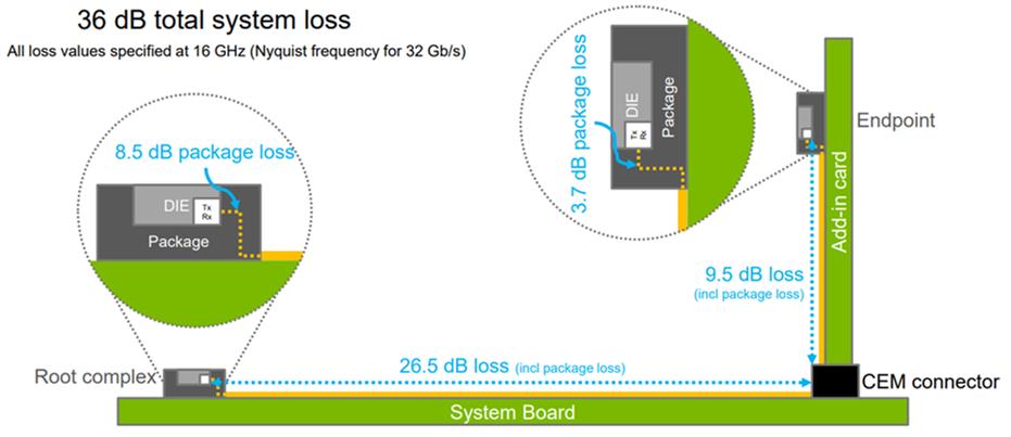
During PCB transmission, higher signal speed means greater attenuation. This is why PCIe 5.0 has stricter requirements for channel, connector loss, and reflection than in previous generations. In PCIe 4.0, the total channel loss budget is 28 dB at 8 GHz. In PCIe 5.0 however, new specifications such as the CPU and AIC die pad packing were added, whiel the channel loss budget was increased to 36 dB at 16 GHz. With the addition of many new specifications during the same time, defining relevant test items according to specifications has also become an important criterion for success.
The tests include the following:
- Transmitter test requirements and methods:
- According to the PCIe 5.0 CEM Specification, the Tx eye diagram of host and AIC cards are as follows:
The current PCIe 5.0 software tool SigTest Phoenix 5.1.0 supports most calibration and test parameters of the basic specifications and CEM specification.
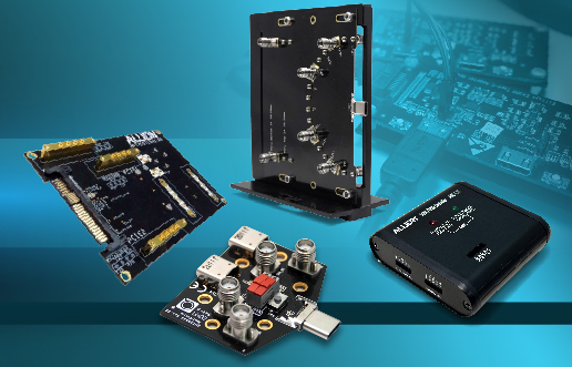
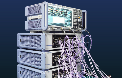
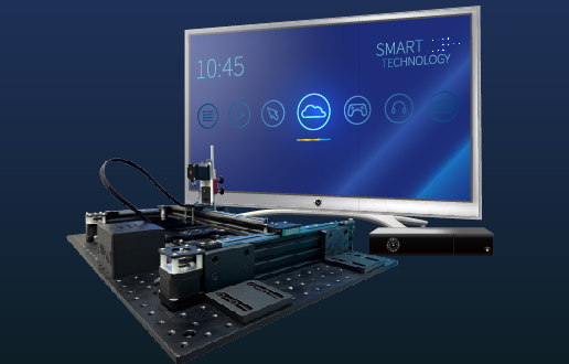
For host testing, 32 GT/s PCIe 5.0 no longer uses the previous dual-port test method. When conducting Tx tests, one just connects the differential signal of the test data lane to the oscilloscope; the reference clock signal does not have to be recorded. Additionally, the Tx test utilizes S-parameter embedding, replacing the variable ISI board to make up for channel insertion loss. In other words, S-parameters other than the fixture and the test cable are embedded in the oscilloscope.1 The following figure illustrates how to connect for accurate 32GT/s PCIe 5.0 system testing.
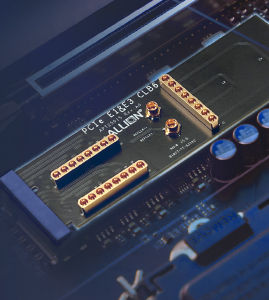
1 Note: Rx tests still require the use of the physical ISI board.
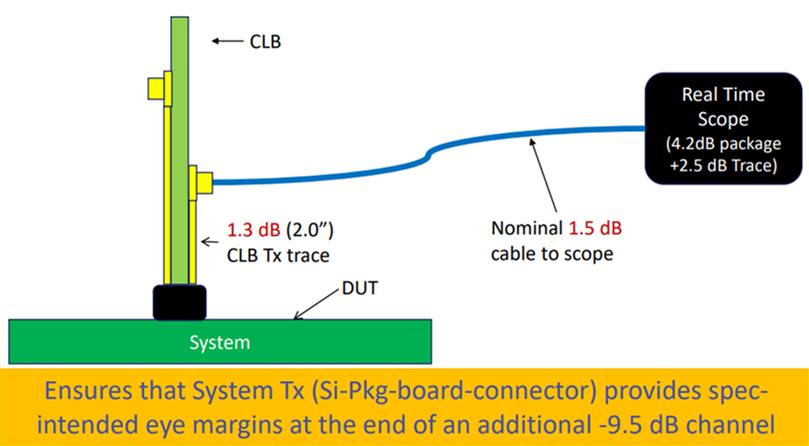
- In the selection of S-parameters, the Vector Network Analyzer (VNA) must be used to measure the CLB loss and cable loss. The values obtained from the VNA are then substituted into the parameters provided by the PCI-SIG.
The oscilloscope settings should be set differently depending on the brand, selecting the test preset to be used. The SigTest Phoenix will then analyze the acquired 2.0M UI waveform to obtain test results.
- Receiver test requirements and methods:
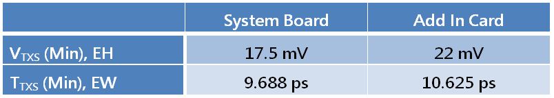
- The PCIe 5.0 receiver test is essentially the same as in the 4.0 version, with the only difference being in calibration. For PCIe 5.0 Rx tests, TP3-point calibration requires the calibration of signal amplitudes at 800mV/720mV, TxEQ, Rj, Sj, as well as the TP 2-point calibration target values of EH 15+/-1.5mV, EW 9.375+/-0.5ps.
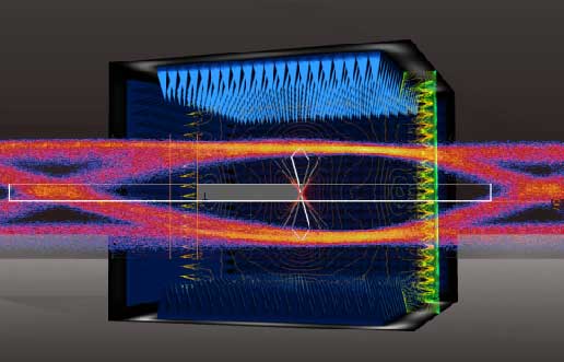
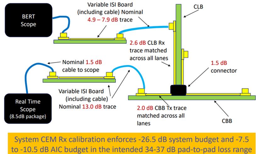
A key point of this test is that the 32 GT/s RX calibration requires the oscilloscope bandwidth to be set to 50 GHz or above, and the sampling rate must be greater than or equal to 128 GSa/s. The complete channel calibration starts from the largest -37 dB (including package loss), searching for the combination of preset and CTLE, then finding the largest EH*EW eye area. We then scan Sj and DMI, and if needed, adjust Vswing in order to calculate whether EH and EW fall in the range of 15+/-1.5mV and 9.375+/-0.5ps respectively. If EH and EW are not in range, the ISI pair should be reduced further, and the process above should be repeated once more. One should note that the preset and CTLE combination should be scanned until the ISI pair is found, the smallest available ISI loss being -34dB. The figure below is the complete channel calibration combination of the system.
If specification requirements are not fulfilled, it may cause an abnormal amount of pressurized jitter and interference parameters, failing to reflect the Rx performance of the DUT.
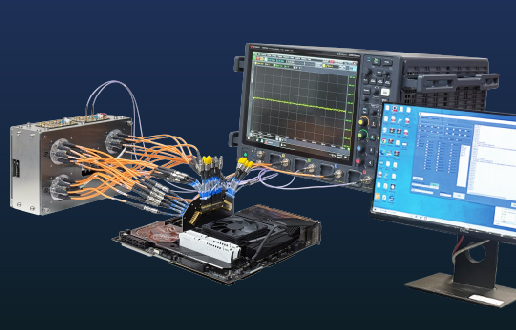
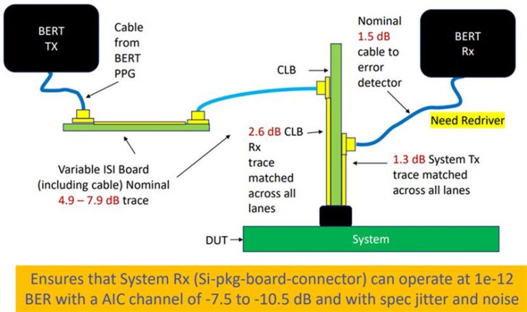
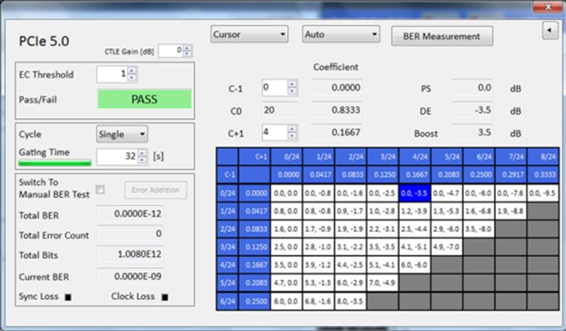
- The Rx LEQ test evaluates the tolerance of the Rx side of the DUT to the pressure signal, reflecting the Rx side’s capability to track jitter and equalize the degraded signal. The evaluation formula is based on the Bit Error Rate (BER). During testing, the DUT must enter loopback mode, where the subsequent BER test is simple. The BER tester sends the Modified Compliance Pattern and 4E12 bits of data; if no more than 1 error occurs, then the DUT passes.
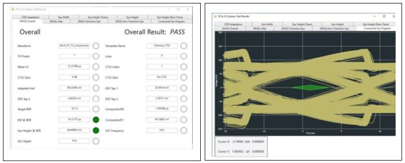
The test connection diagram and results are as follows:
In summary, Allion has invested in high-precision oscilloscopes and Bit Error Rate Testers for PCIe 5.0 PHY testing for both Tx and Rx sides. We assist our clients to obtain maximum gain through their investments, and contribute to the development of new PCIe 5.0 products through our experienced engineering team and world-class test equipment.
If you have product verification or various customized measurement requirements, please contact us at: service@allion.com