


The Allion Cabcon Lab has assisted clients for many years, often encountering tight deadlines due to shipments. Failure to pass inspections is an important issue that must be solved in the early stages of product design, material inspection, and the manufacturing process. Not only does inspection failure waste time, but it also increases development costs. If you can control the quality of products in each process, you can reduce most problems before shipment.
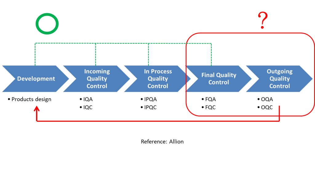
Before talking about the analysis of defective products, the first thing to understand is the various inspections and management processes that the production line will encounter. In a basic quality control process, these steps are included:
- Incoming Quality Control (IQC)
- In Process Quality Control (IPQC)
- Final Quality Control (FQC)
- Outgoing Quality Control (OQC)
Read more about Quality Control – The Key to Successful Products
This article will focus on important matters in product development, incoming materials, and process control. If you pay more attention to the details and characteristics of the design and material during the beginning and middle stages, you can safely send out your shipment without worrying.
1. Product Development
In the early stages of development, engineers must conduct testing and comparisons of each component and decide which components are manufactured in-house and which are outsourced. They also confirm the design, assembly, and compatibility. The common precautions are listed below.
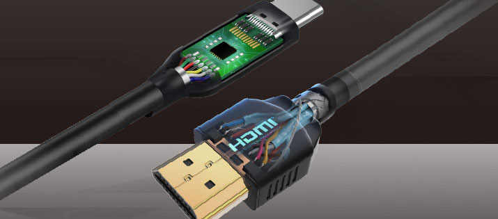
A. Component Selection
During assembly, in addition to paying attention to the quality and mechanical strength of the connector, raw cable, and paddle card, it’s also necessary to identify the type of glue that’s coated in the processing area. The characteristics, convenience of processing, moisture content, and curing time of the glue must be taken into consideration.
B. Component Characteristic Loss Margin
When selecting cable materials, a loss margin must be reserved for the connector. Taking the budgets of Type C Gen2 as an example, the loss margin of the host and device is about 8.5 dB, and the loss margin of the finished wire is 6 dB. At this time, if the cable’s characteristic already exceeds 5 dB at 5 GHz, adding a connector and processing loss is likely to exceed the range.

USB Type C to C Gen2 Loss Budget (Reference: USB IF)
C. Paddle Card Control
The PCB layout factory designed the trace and pad according to the specifications. After the design was complete, the wire supplier obtained the paddle card and soldered and glued the wires, only to find out the impedance dropped due to processing. This causes an increase in impedance discontinuity, shown in the figure below. This means that the manufacturer and the layout factory didn’t discuss the next step and the effects of processing when signing the contracts. The correct approach is to first estimate the difference in the impedance after processing and increase impedance when designing the layout so that the waveform falls into the correct area.
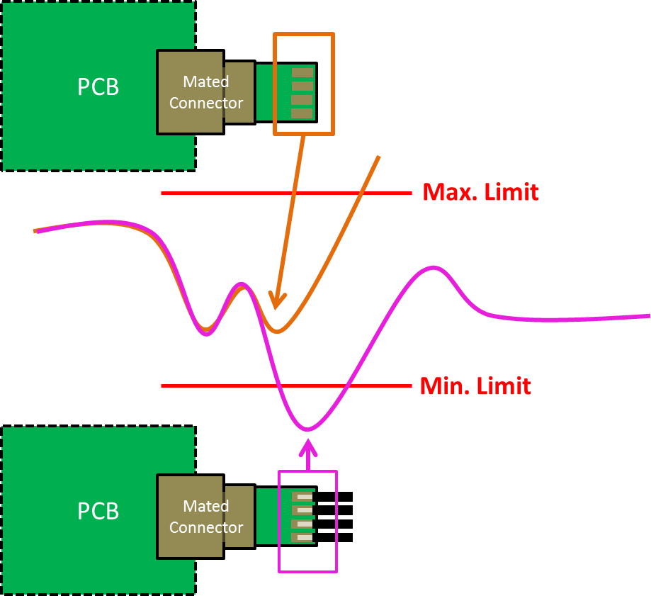
Differences in the paddle card before and after welding (Reference: Allion)
D. Process Design
- The length to be stripped of each layer of the cable must be clearly defined, and the parameters of the stripping machine should be set according to these specifications. When using a laser stripping machine, the energy and focus of the upper and lower rows must also be clearly defined.
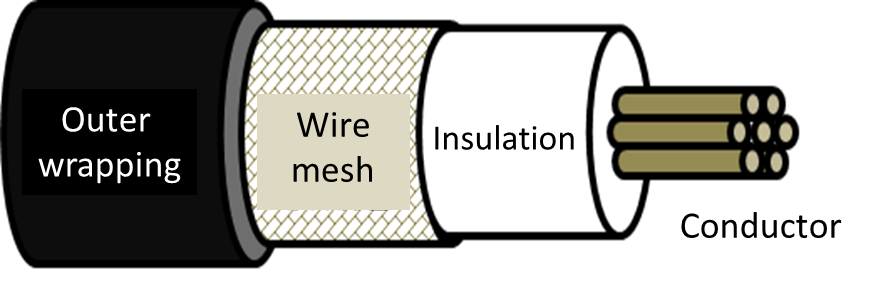
Coaxial Cable Structure (Reference: Allion)
- Soldering must be done according to the paddle card’s design to select the correct machine. If HotBar is used, the type of press, stroke settings, pressing time, and other parameters also need to be considered.
- If you choose to use braiding or taping, the traditional horizontal machinery may affect the coating due to gravity. However, vertical machines can improve uneven coating because the direction of operating is perpendicular to gravity.
2. IQC
It’s very important to check all of the components. If the structure and characteristics of the components expected to be mass-produced do not match the specifications, they must be found before production, or else more issues might surface such as loss of time or costs. The following are some common problems:

A. Raw Cable
- Is the cable structure correct? (Ex: If the arrangement and combination of the outer layer, ground wire, and cables are wrong, it may cause low crosstalk)
- Is the impedance design correct? (Ex: Is the waveform smooth?)
- Is the insertion loss as expected? (If the attenuation is larger than the evaluation value, it may cause it to have defects)
- Is the conversion loss too high? (This may also be caused if the insulation layer is uneven or the cable length difference is too large when drawing wire)
- Does the weaving density reach the indicated percentage? (Ex: Affects EMI)
B. Connector
- Is the positive terminal normal? (Ex: Terminal offset is likely to cause poor high-frequency characteristics, especially crosstalk)
- Does the terminal have burrs? (Ex: Burrs tend to increase the loss of material)
- Does the SMT terminal spacing conform to the design? (Ex: Inconsistent spacing makes aligning with the paddle card difficult)
C. Paddle Card
- Is the impedance design correct? (Ex: The impedance will drop lower after soldering, affecting the results)
- Is the ground loop correct? (Ex: Defective ground loops are prone to low crosstalk)
- Do the signals interfere with each other when they change between different layers? (It’s easy for this to affect impedance and crosstalk when they’re too close together)
- Does the cutting board affect the size of the board edge? (Ex: Inconsistency in size can cause difficulty during assembly, which will also affect high-frequency characteristics)
3. PQC
When confirming that everything is ready to enter the production process, it’s necessary to ensure all processes during production are planned and the equipment is adjusted. This is because there might be small errors between the ideal parameters of various equipment and the actual situation. If the parameters of the equipment are inconsistent, it may cause the final product’s characteristics to drop below expectations. Here are some common situations below:
- Is the cutter sharp?
- Are the SMT and connectors misaligned?
- Is the temperature too high when soldering? This will cause shrinkage and deformation of the cable.
- Is the cable core bifurcated or loose during soldering?
- Are there solder balls, empty soldering, or short-circuiting?
- Is the coaxial braid completely covered?
- Does the glue affect the impedance?
- Is the glue on the inner membrane dry?
After the explanation above, we’ll share some common bad cases encountered during testing. In the examples below, the item that failed and the reason for it are briefly explained.
Case 1
- Pay attention to the heating times during soldering to avoid excessive heat that can result in shrinkage or damaging the outer core.
- It’s recommended not to peel off too much aluminum foil during processing. Aluminum foil can help with impedance control.
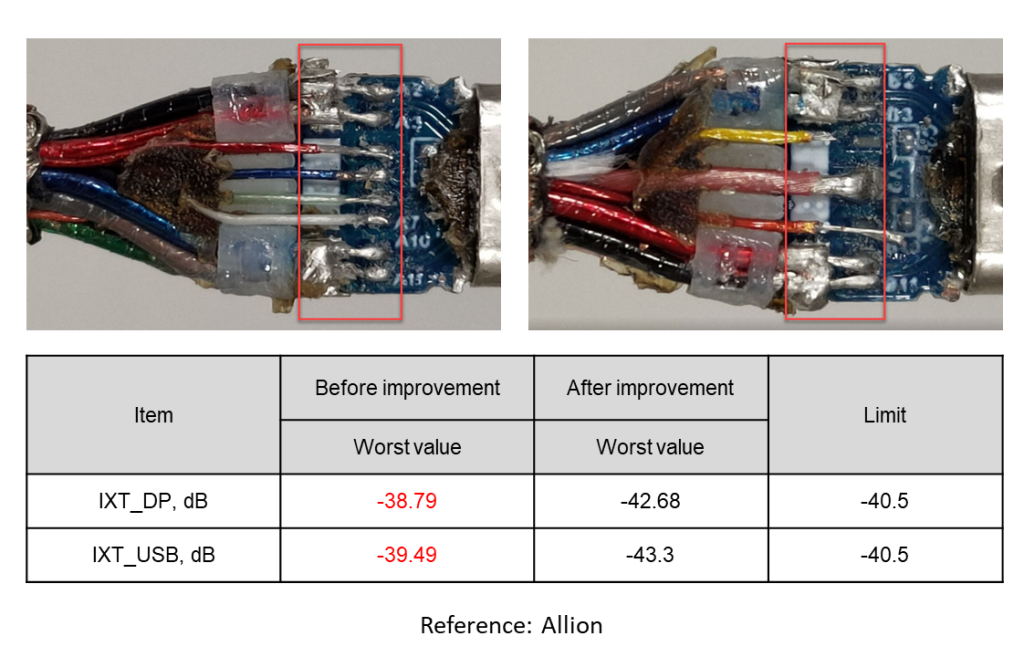
Case 2
Controlling the amount of tin and the spacing of the joints to avoid crosstalk.
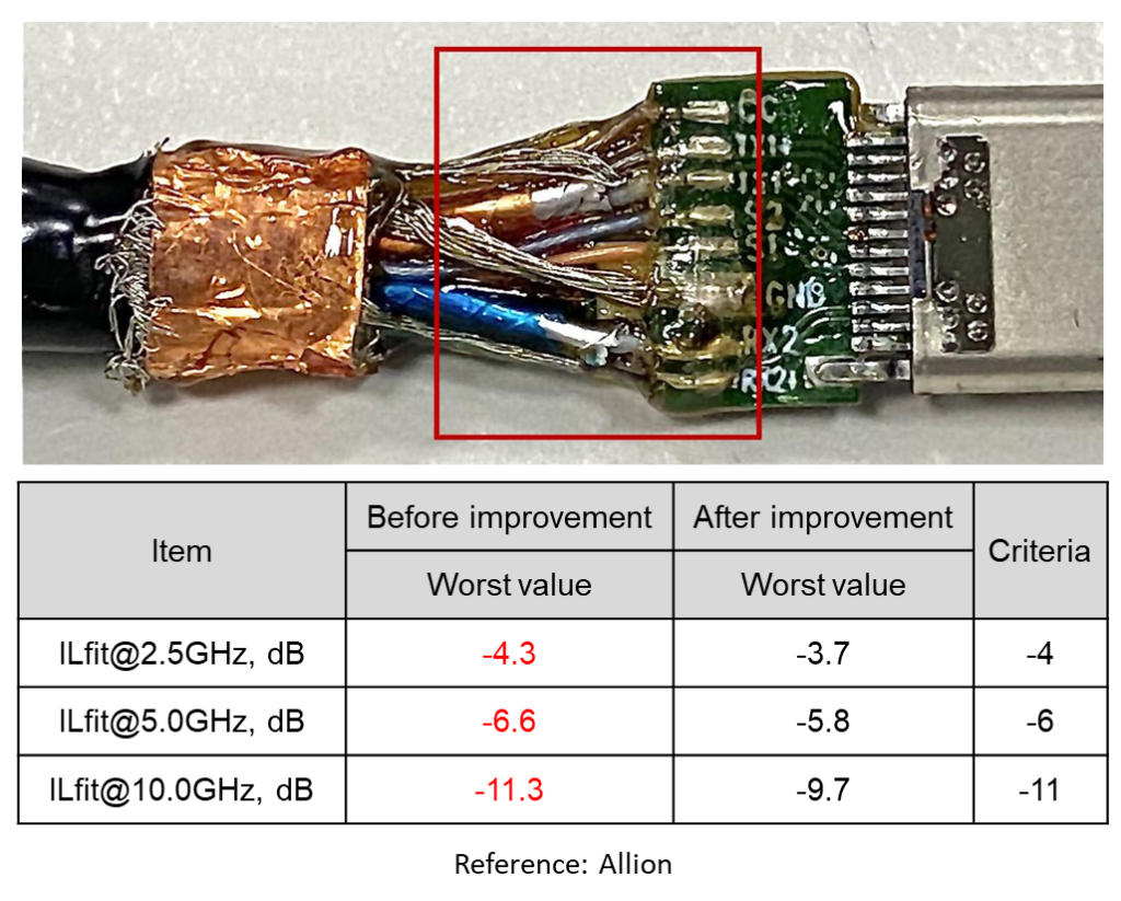
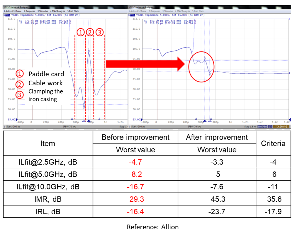
Case 3
The impedance of the components and different sections are too large and have too many, failing IL Fit, IMR, IRL, and others.
There are many reasons for poor high-frequency measurements. The same test item can be affected by different or combined factors. Allion always adheres to the most serious attitudes and rapid response times when dealing with testing. The comparison and confirmation of methods and waveforms allow us to provide our clients with the best suggestions, helping them obtain faster solutions no matter the difficulties they face in the early stages of development or certification.
If you have any requirements or questions, please contact us.