


Allion Labs | Tina Yu
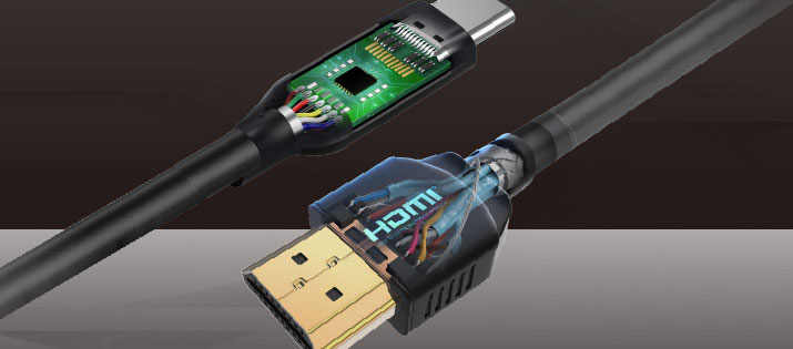
On the packaging of HDMI-enabled products, one can often find the HDMI logo on its packaging. This mark means that the product complies with HDMI specifications required by the HDMI Forum, allowing the product to be sold on the market.
HDMI Logo (Source: HDMI)
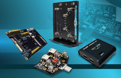
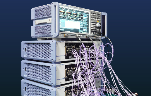
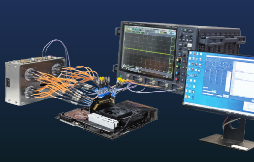
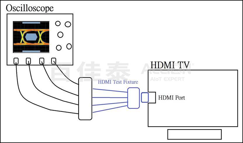
The HDMI Forum requires all HDMI-enabled products to pass the HDMI certification test, in which HDMI test fixtures play a vital role. Test engineers utilize test fixtures specially designed to measure the necessary electrical characteristics and related parameters. The measurements are then analyzed to determine whether the DUT passes or fails the test, completing the HDMI certification test.
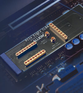
HDMI test fixtures act as bridges, connecting the 19 pins inside an HDMI connector to test equipment so test engineers can access the required parameters for different test items.
Potential Risks of HDMI Test Fixtures
An excellent fixture correctly measures the electrical parameters of HDMI products and avoids affecting the electrical properties of the DUT.
On the contrary, a problematic fixture affects the measurement of electrical parameters of the DUT, even causing it to fail the test.
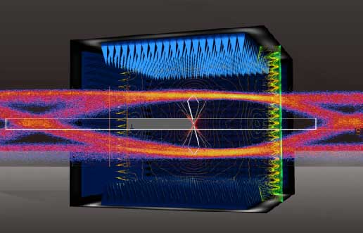
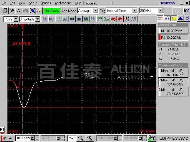
HDMI specifications consider the DUT to have failed the electrical test when electrical parameters fall below 75Ω. In the figure below, the red wave pattern shows the electric parameters when the DUT is connected via SMA cables to the test equipment, indicating the DUT passes the test. Yet, the white wave pattern, signifying electric parameters upon fixture connection, shows a false measurement value of below 75Ω. This test fixture affects the test values drastically, illustrating its incapability of proper measurement and failure to comply to fixture standards. We can thus conclude that the quality of a fixture can drastically alter the outcome of testing.
How to Ensure Fixtures Adhere to HDMI Specifications
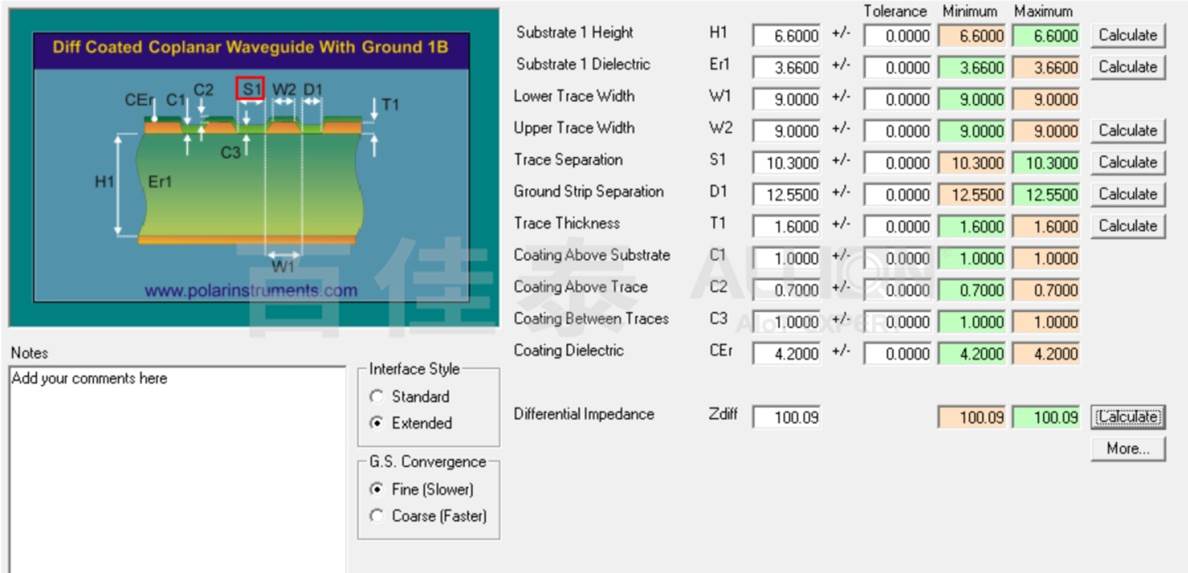
The newest HDMI 2.1a Specification defines connector requirements as follows:
- Impedance: 100Ω±10% (Note: A single excursion is permitted out to a max/min of 100Ω±15% and of duration less than 150ps)
- In comparing connector and cable requirements, one can see that the requirements for the connector-end are the same. When impedance complies to the requirements, the fixture will not affect test results.
- Design Considerations:
The connector should be a CAT3-compliant connector.
The PCB board itself should be a high-frequency material (e.g. Rogers).
The trace width should adhere to necessary impedance requirements through software calculation.
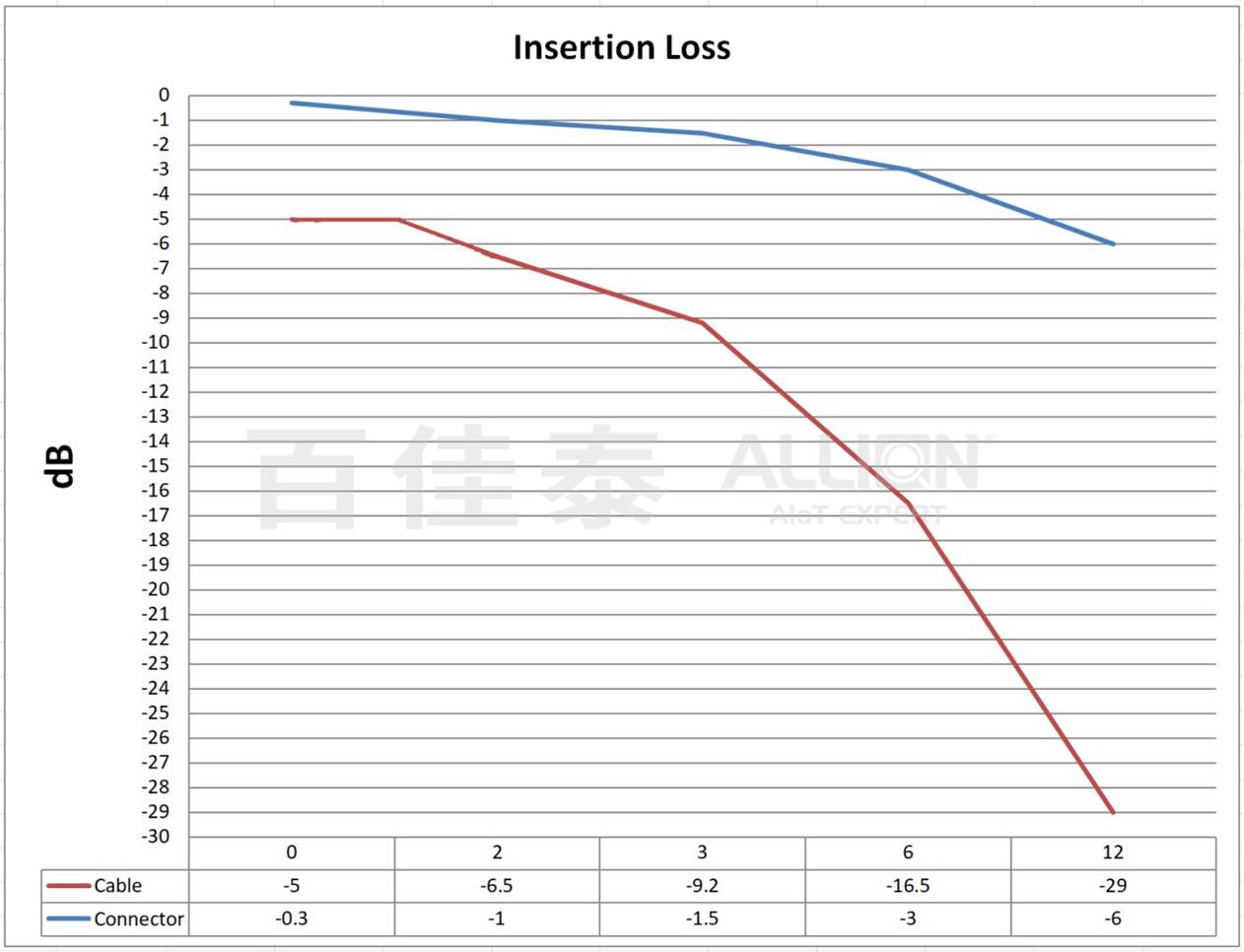
- Insertion Loss: from 0.3dB to 6dB at 12GHz
- In comparing connector and cable requirements, the figure below shows connector requirements are higher than cable requirements, thus the design must meet or exceed stated requirements to avoid affecting the test.
The design must avoid excessive signal loss in PCB traces (e.g. lowering reflections between multiple trace materials or reducing stubs caused by plated vias)
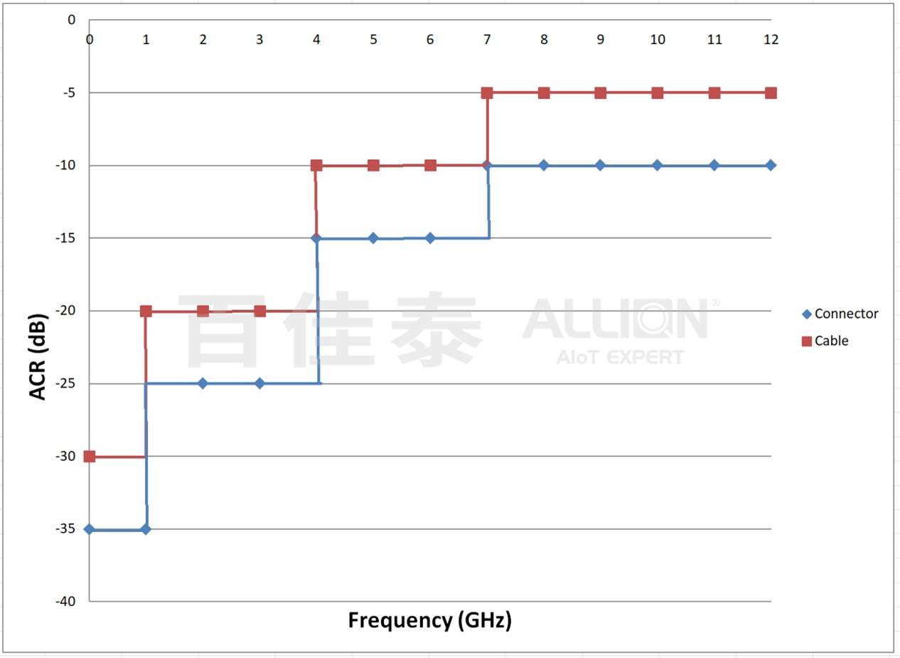
- ACR (Far-End): from -35dB to -10dB over the frequency range 0-12GHz
- In comparing connector and cable requirements, the figure below shows connector requirements are higher than cable requirements, indicating the fixture must adhere to the high requirements in order not to affect test results.
- Design Considerations:
Insertion Loss should comply with requirements.
Crosstalk should either adhere to the 3W rule or utilize methods like via fences in order not to affect test results
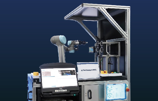
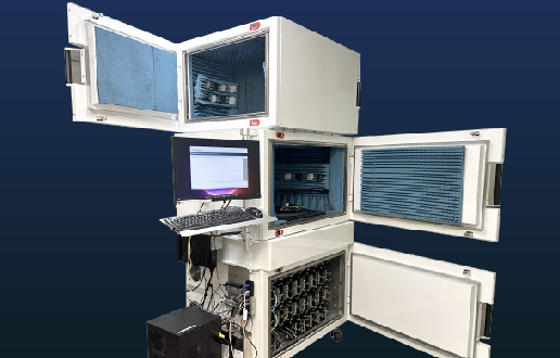
Allion Provides High-Frequency Measurement and Customized Fixture Design
Allion is currently the only test lab capable of providing comprehensive high-frequency testing and customized fixture design. Our services encompass fixture design, validation testing, design improvements, and certification tests. Our role is to reduce the time needed in your product development process while ensuring product quality and competitiveness on the market.
If you have any high-frequency testing or test fixture needs, please feel free to contact Allion by email or browse our fixtures.