


As a result of a proposed standard ratified by the European Union (EU), future smartphones, tablets, and cameras are bound to adopt USB Type-C charging interfaces in the autumn of 2024. The new regulation is expected to make Type-C connectors even more common in electronic products within the next few years. Allion, a veteran of USB testing and certification, works closely with the association to ensure customer designs meet certification standards from product development to launch, ensuring a fast and easy certification process.
This article discusses the key factors manufacturers should keep in mind when designing connectors. By paying attention to design details, manufacturers can save time and money during development and ensure that the finished product passes certification tests smoothly.
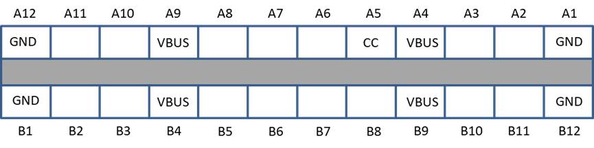
I. Basic requirements for Type-C connector certification: number of contacts
USB Full-Featured Type-C Receptacle: 24 contacts ( A1 – A12 and B1 – B12)
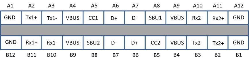
USB Type-C Receptacle Interface (Front View)
USB 2.0 Type-C Receptacle:
16 contacts A1, A4, A5, A6, A7, A8, A9, A12, B1, B4, B5, B6, B7, B8, B9, and B12.
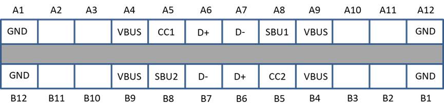
USB 2.0 Type-C Receptacle Interface (Front View)
USB Full-Featured Type-C Plug:
22 contacts: A1 – A12 and B1 – B12, with contacts B6 and B7 depopulated; or
24 contacts: A1 – A12 and B1 – B12
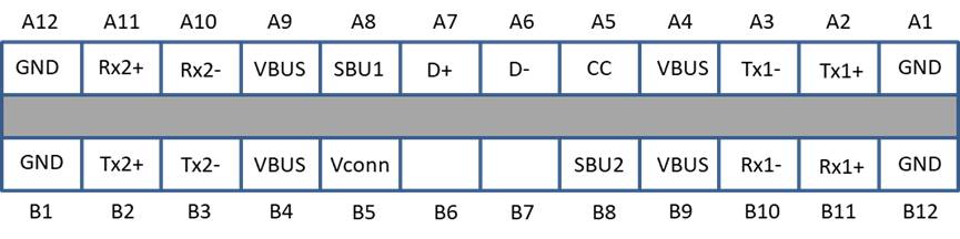
USB Full-Featured Type-C Plug Interface (Front View)
USB 2.0 Type-C Plug:
12 contacts A1, A4, A5, A6, A7, A9, A12, B1, B4, B5, B9, and B12
14 contacts A1, A4, A5, A6, A7, A8, A9, A12, B1, B4, B5, B8, B9, and B12
14 contacts A1, A4, A5, A6, A7, A9, A12, B1, B4, B5, B6, B7, B9, and B12
16 contacts A1, A4, A5, A6, A7, A8, A9, A12, B1, B4, B5, B6, B7, B8, B9, and B12
USB 2.0 Type-C Plug Interface (Front View)
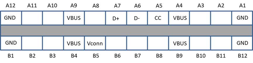
USB Type-C Power-Only Plug:
9 contacts A1, A4, A5, A9, A12, B1, B4, B9, and B12
USB Type-C Power-Only Plug Interface (Front View)
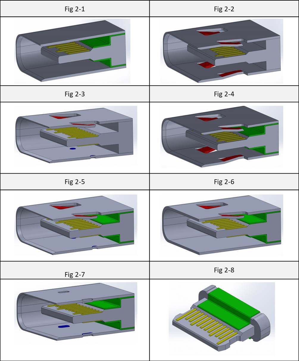
II. Types of certifiable Type-C Receptacle connector structural design:
- There are upper and lower EMC pads in the internal structure (Fig 2-1).
- The metal shell is designed with shrapnel at the top and bottom (Fig 2-2).
- There is shrapnel on top and convex hull on bottom of the shell, or convex hull on top and shrapnel on bottom (Fig 2-3).
- Shrapnel is designed into the top and bottom of the shell, and EMC pads are included in the internal structure of the shell (Fig 2-4).
- There is shrapnel on top and convex hull on bottom of the shell, or convex hull on top and shrapnel on bottom, and EMC pads are included in the internal structure of the shell (Fig 2-5).
- The plug shell is designed with one-sided shrapnel, with internal EMC pads on both top and bottom (Fig 2-6).
- There is convex hull on top and bottom of the shell, with internal EMC pads on both sides, and the distance between the convex hulls must exceed the size of the Plug for certification to be successful (Fig 2-7).
- In the absence of a shell design, the structure must include EMC pads both on top and bottom (Fig 2-8).
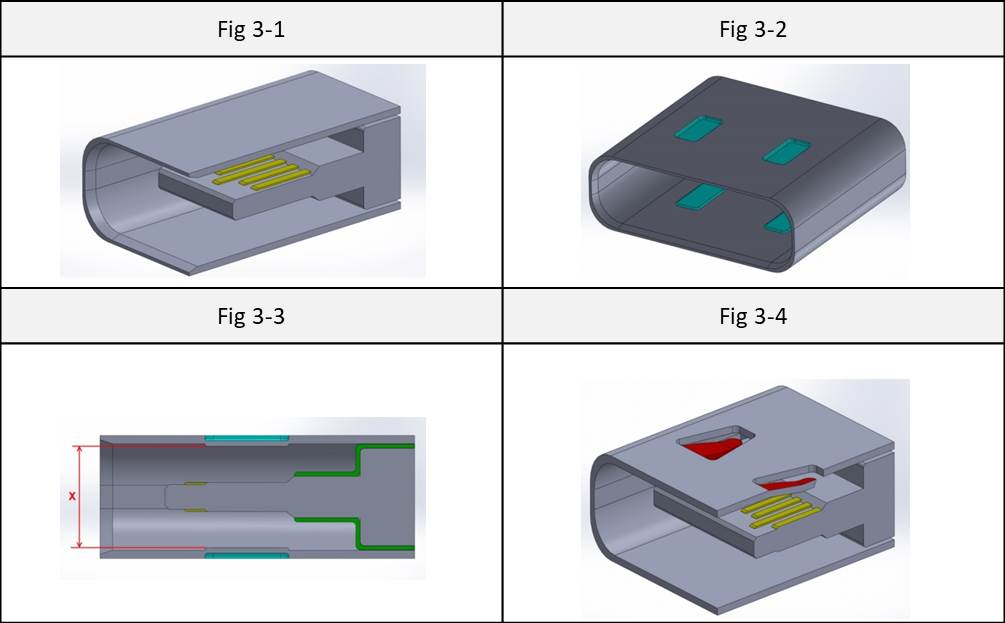
III. Types of NON-certifiable structural design of the Type-C Receptacle connector, according to the association:
- This receptacle does not have an outer shrapnel design or an EMC pad inside (Fig 3-1).
- Convex hulls cover both sides of the Receptacle’s shell (Fig 3-2).
- The receptacle’s outer shell has a convex hull (whose height is considerably lower than the maximum dimension (x) of the plug’s thickness and width), and its interior has EMC pads on top and bottom (Fig 3-3).
- The receptacle’s outer shell only has one side of EMC, and there is no EMC pad inside (Fig 3-4).
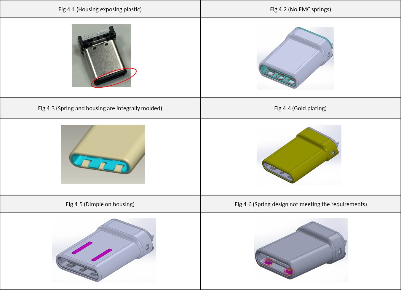
IV. Types of NON-certifiable Type-C Plug connector design, according to the association:
- Plastic exposed at the housing opening (Fig 4-1).
- The internal structure design lacks EMC springs (Fig 4-2).
- The shell and springs are integrally molded (Fig 4-3).
- Metal shell is plated with precious metals (Fig 4-4: Gold plating).
- Shell with solid bumps or dimples (Fig 4-5).
- EMC spring design not meeting the specified requirements for certification (Fig 4-6).
Besides helping customers with connector testing needs, Allion will also verify the initial product design concept with the association to ensure that the design meets all specified requirements. We provide comprehensive testing and certification services to assist customers in obtaining accurate information quickly and efficiently.
If you have any requirements or questions, please contact us.