


In recent years, the proportions of desktop computers combined with Wi-Fi and Bluetooth functions have been increasing gradually. The advantage is that the location of a computer will not be limited by Ethernet (LAN) connection, while the computer can connect with Wi-Fi and Bluetooth devices at any time. This makes desktop computers far more convenient.
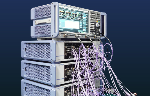
On the market, it is very common to see high-end motherboards combined with Wi-Fi and Bluetooth network interface cards, because they are very convenient for users. However, the barriers and costs of ODM development will also increase. The mainstream desktop computer developers have RD backgrounds serving as electronics-related backgrounds. Larger developers will prepare dedicated RF Engineer Teams, to conduct the designs, testing, and integration related to radio frequency (RF), while ensuring a certain degree of communication quality of the circuits for wired signals (LAN) and wireless signals (Wi-Fi/Bluetooth).
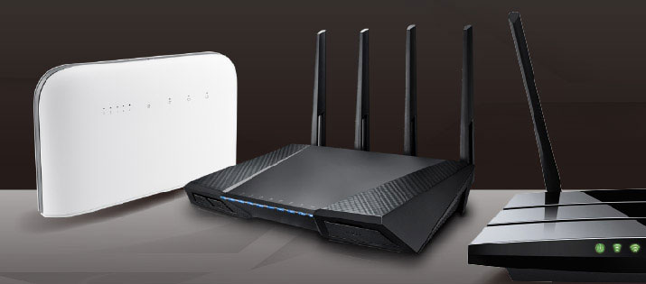
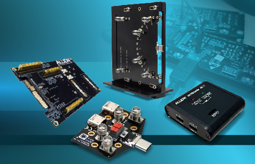
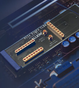
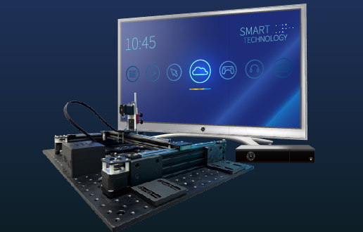
Various desktop computers equipped with hidden antennas or external antennas
According to our many years of testing experience, the smaller desktop computers designed by ODM usually have throughput irregularity problems. After the discussions held by three parties (namely our company, Original Design Manufacturers (ODM), and antenna suppliers), we ruled out problems one by one based on multiple directions, ranging from basic design specifications, antenna designs, hardware circuit layouts, mechanism designs, and driver confirmation. Usually, many tiny problems may increase accumulatively. If you just handle one or two of these problems, the throughput testing may not have significant improvement in the end. Through a case study, this article presents the analysis of an introduction to Wi-Fi communication quality problems.
Generally, when executing RF Performance Debugging, we can follow the following procedures for making confirmation, in order to reduce the possibility of wrong directions before problems are found:
Allion suggests the following:
- First, confirm the throughput testing data at the original state (i.e. Baseline Data), so that the data can serve as the reference for subsequent modification and comparison.
- Confirm the correctness of basic software, firmware, and OS, or whether there is a known issue that should be identified. The following example can serve as a reference.
- The “Yellow Bang” must not appear in Device Manager, because “Yellow Bang” means that the diver installation of the device is incomplete and the device is in an abnormal working state, so the following might happen:
- Network Interface Card: The user cannot make sure whether the state is working normally, which may result in problems related to throughput or connection.
- Graphics Card: Incomplete driver installation may cause a graphics card to have frequency changes or be at a constant full power state, thereby interfering with the frequency band of Wi-Fi/Bluetooth.
- USB Device: The differential signaling frequency of “USB 3.X” is 2.5GHz, which may cause interference to Wi-Fi/Bluetooth. When the device is not in use, it should be truly turned off, in order to avoid interference with Wi-Fi/Bluetooth performance.
- Make sure that the antenna performance meets the needs. If not, a small adjustment must be done because the antenna is the part that can affect high-frequency performance most directly. If the operation frequency of the antenna has any deviation, the throughput data and transmission distance will deteriorate immediately, so the VSWR and Isolation performance parameters need to be confirmed or the antenna patterns should be checked further.
- Identify the problems caused by noises. The so-called “noise” means any unnecessary signal in a communication system. Noises include standardized signals, thermal noises, clock signals, etc., which do not belong to the transmission system. For instance, when Wi-Fi and Bluetooth are working at the same frequency simultaneously, they are mutual noises to each other. The noises will cause poorer throughput and transmission distance. Usually, there are two paths in which the noises can affect the entire system, namely via the conduction paths through “Radiation Noise” and “Conductive Noise”.
- Possible causes of Radiation Noise interference:
- Confirm the fitness of the metal shield in the mechanism, to see whether there are any structural holes and gaps that cause noise leakage and then interfere with an antenna.
- Confirm that the parts with higher noise radiation strength inside a product can be shielded (e.g., metal coverage, metallic tape, etc.)
- Possible causes of Conductive Noise interference:
- Noises are transmitted to all areas or spaces, through the transmission cables as well as the components on the circuit boards.
Then, we follow the above-mentioned procedures to do troubleshooting, for ruling out problems step by step.
- The throughput testing data (i.e. baseline data) of the object to be tested at its original state
The following table indicates a supplier’s specifications of Wi-Fi throughput, as well as the first throughput testing on the original equipment.
| Frequency Band | Bandwidth | Channel | ANT
QTY |
TX/RX | 20m
Simulation of decay distance |
100m
Simulation of decay distance |
||
| SPEC
(Mbps) |
Test Result (Mbps) | SPEC
(Mbps) |
Test Result
(Mbps) |
|||||
| 11n 2.4GHz | HT20 | CH1 | 2×2 | TX | 70 | 103.00 | 40 | 91.96 |
| RX | 70 | 27.73 | 40 | 9.20 | ||||
| CH11 | TX | 70 | 105.30 | 40 | 91.16 | |||
| RX | 70 | 34.88 | 40 | 8.20 | ||||
| HT40 | CH11 | 2×2 | TX | 120 | 186.57 | 40 | 145.55 | |
| RX | 110 | 50.63 | 40 | 22.95 | ||||
| 11n
5GHz |
HT20 | CH36 | 2×2 | TX | 70 | 115.85 | 30 | 91.19 |
| RX | 70 | 98.10 | 30 | 40.11 | ||||
| CH64 | TX | 70 | 116.13 | 30 | 89.55 | |||
| RX | 70 | 101.94 | 30 | 51.46 | ||||
| CH100 | TX | 70 | 115.96 | 30 | 85.54 | |||
| RX | 70 | 110.53 | 30 | 95.66 | ||||
According to the specifications and testing items defined by customers, the RX at 2.4GHz Band in the ground color of yellow indicates “Fail”. In the specification of 20m distance, there is a discrepancy up to 42.3Mbps in the data (shown in red words), while the discrepancy is up to 31.8Mbps in the specification of 100m distance. Then, as for the aspects such as system software and drivers, we confirm whether the correct versions are installed correctly and completely.
- Confirmation of software, system versions, and drivers
After we confirm that the Windows version is correct and there is no Yellow Bang in the Task Manager List, this means that the drivers in all the different hardware are correct. Next, we’ll check the antenna.
- Antenna confirmation
As for hardware, we must confirm the situation of VSWR as well as the Isolation of the antennas on products. It is very easy to measure the performance of the two antennas, and we can rapidly inspect the basic performance of the antennas.
- VSWR (Voltage Standing Wave Ratio)
Able to rapidly measure whether there is any deviation in the operating frequency of the antenna combined with the mechanism of the object to be tested, the general VSWR standard in the industry needs to be less than 2. The closer the number gets to 1, the better the antenna’s features will be.
- Isolation
As for the measurement of the isolation feature, such a measurement needs to be conducted only when a product has multiple antennas. The purpose is to identify whether there is any inter-interference between the antennas when receiving and sending signals. The interference may cause the overall reduction of RF features. Generally, the Isolation standard in the industry is about -20~-30dB. The smaller the value, the better the Isolation effect will be. A Network Analyzer can be used for confirming the performance data of VSWR as well as the Isolation of the antenna.
| Antenna | Main | Aux | ||||||
| 2.4 GHz | 2.5 GHz | 5.15GHz | 5.85 GHz | 2.4 GHz | 2.5 GHz | 5.15GHz | 5.85 GHz | |
| VSWR | 2.24 | 4.49 | 1.18 | 3.88 | 1.59 | 2.47 | 2.93 | 2.63 |
- VSWR
In the column of the main frequency band, the VSWR is 4.49 (shown in red words) in the 2.5GHz frequency band, which is poorer than that of 2.4GHz. From the curve diagram, we can know that the antenna’s operation frequency band has deviated to the lower frequency, which affects the throughput of the 2.4GHz frequency band. However, due to material control and management problems, customers cannot make any structural adjustments to the antennas at the current stages. All they can do is make modifications to the chassis. Thus, let’s confirm the Isolation data next, to see whether we can make some improvements.
| Antenna | 2.4 GHz | 2.5 GHz | 5.15GHz | 5.85 GHz |
| Isolation
(dB) |
-11.23 | -14.9 | -22.29 | -29.73 |
- Isolation
The Isolation values at the frequencies of 2.4GHz and 2.5GHz are respectively -11.23 and -14.9dB (shown in red words). The general standard in the industry is -20dB. The measured values are almost 10db less than the general standard in the industry, so improvements must be made in Isolation, too.
“Gap distance between two antennas” and “polarization” are the two factors mainly affecting the Isolation features. From product’s appearance, we can see that both antennas are on the front wall at a distance of merely about 3 cm (shown in the left picture below). The locations of the two antennas are in staggered polarization, so we conclude that Isolation is deteriorating probably because the distance is too close. To validate this hypothesis, an isolation material is placed in the middle between the two antennas (shown in the left picture below) to simulate an enhancement in the Isolation between the two antennas. The Network Analyzer (NA) is used for conducting an Isolation measurement respectively with isolation materials (copper foil and noise absorber) and without any isolation material. After the isolation material has been included, the findings indicate that the 2.4GHz Isolation is improved from -12.23dB to -14dB, while the 2.5GHz Isolation is improved from -14.9dB to -16.5dB (shown in the right picture below).
| Isolation material |
| Antenna 1 |
| Antenna 2 |
| Blue Line – Isolation material: copper foil
Yellow Line -Isolation material: noise absorber Red Line- No isolation material |
| Isolation |
Then, let’s validate and compare the throughput. From the table below, we can see that the Channel 1 20m 23.05Mbps is improved to be 37.52 ~ 47.38Mbps as long as we include the isolation material. In the 100m, it is improved from 6.5Mbps to 11.24~18.32Mbps. The improvement of the Isolation can indeed enhance the throughput data.
| Throughput
11n_RX AVG.(0o) Unit: Mbps |
CH1 BW20 | ||
| No isolation material | Isolation material_ noise absorber | Isolation material_ copper foil | |
| 20m | 23.05 | 47.38 | 37.52 |
| 100m | 6.5 | 18.32 | 11.24 |
After the foregoing Isolation optimization and throughput validation, we have proven that the hypothesis of “the distance is too close between the two antennas” is correct. So, customers and our company immediately discussed how to change the locations of the antennas. Instead of the previous approach in which two antennas were set up on the same front wall, we equip the front wall and the rear wall respectively with an antenna each, to improve the Isolation problem. The schematic diagrams indicating the new locations of the antennas are shown as follows, while the comparison of the throughput testing data is also presented.
| Antenna on the front wall |
| Antenna on the rear wall |
The modified objects to be tested have undergone the throughput testing again, and the results are shown as follows:
| Frequency Band | Bandwidth | Channel | ANT
QTY |
TX/RX | 20m
Simulation of decay distance |
100m
Simulation of decay distance |
||||
| SPEC | Antennas on the front wall*2
Test Result |
Antenna on the front wall *1
Antenna on the rear wall *1 Test Result |
SPEC | Antennas on the front wall *2
Test Result |
Antenna on the front wall *1
Antenna on the rear wall *1 Test Result |
|||||
| 11n 2.4GHz | HT20 | CH1 | 2×2 | TX | 70 | 103 | 105.97 | 40 | 91.96 | 94.24 |
| RX | 70 | 27.73 | 74.07 | 40 | 9.2 | 19.44 | ||||
| CH11 | TX | 70 | 105.3 | 107.48 | 40 | 91.16 | 94.27 | |||
| RX | 70 | 34.88 | 59.65 | 40 | 8.2 | 16.69 | ||||
After we change the locations of the antennas, the throughput data indicate a significant improvement, from 27.73 to 74.07 in the RX Channel 1 20m. The testing result becomes “PASS”. The distances with the other channels have also been enhanced as well. Thus, the antenna itself and the design of the antenna layout can directly affect the throughput testing results. End-users may certainly be aware of poor antenna designs, so customer complaint rates may increase, which can directly affect goodwill in the market.
Careful readers may have spotted that the values in Throughput RX Channel 1 100m, Channel 11 20m, and 100m still indicate “Fail”, especially the value of 16.69~19.44Mbps in 100m high attenuation, which merely accounts for less than half of the SPEC; however, the TX value is very good. This phenomenon is usually caused by the interference of noises. Thus, we should continue going on Step 4 “RF Performance Debugging: Noise Measurement and Troubleshooting”. As for relevant testing data, we will conduct an objective analysis of the actual testing data in the following article, so that manufacturers and designers can have a better understanding of what they should pay attention to, in terms of RF performance in product design.