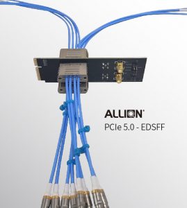


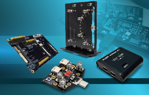


Continuing from the last article, we will introduce the related functions of the Allion U.2/U.3 (APT21071) Test Fixture. As mentioned before, this test fixture can be used to measure SAS and PCIe signals simultaneously.
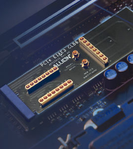
A. U2/U.3 connector
Using the newest SAS connector, it can meet the specifications of SAS4 and PCIe.
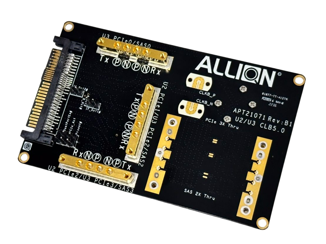
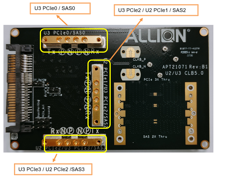
B. Front
There are three sets of SMPM Connectors on the front side, which are used to measure three different signal configurations.
-
When testing a U.3 test interface, the three sets of connectors can be used to measure PCIe0 (top), PCIe2 (middle), and PCIe3 (bottom) of the interface.
-
When testing a U.2 test interface, two of the connectors can be used to measure PCIe1 (middle), PCIe2 (bottom) of the interface.
-
When testing a SAS test interface, three sets of connectors can be used to measure SAS0 (top), SAS2 (middle), SAS3 (bottom) of the interface.
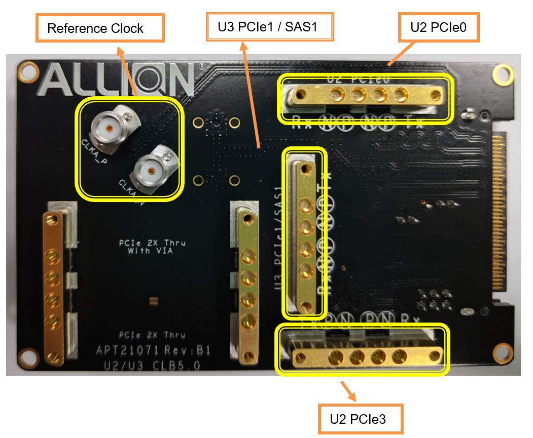
C. Back
There are five sets of SMPM Connectors on the back (three for signal measurement and two for calibration) and two SMA connectors for the Reference Clock
- When testing a U.3 test interface, only one set of connectors can be used to measure the PCIe1 (middle right) signal of the interface.
- When testing a U.2 test interface, two of the connectors can be used to measure PCIe0 (top right) and PCIe3 (bottom right) of the interface.
- When testing a SAS test interface, only one set of connectors can be used to measure the SAS1 (middle right) signal of the interface.
- Reference Clock is used to connect Clock to Scope (top left)
- Two sets of SMPM Connectors are used for calibration purposes (bottom left)
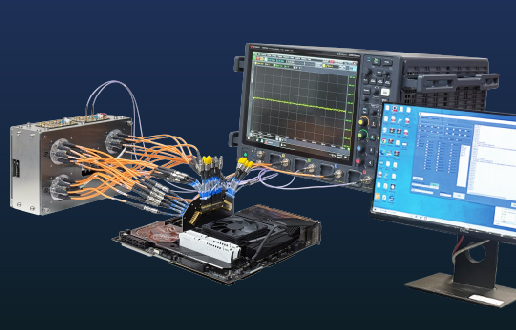
Based on Allion’s domain knowledge for validation testing throughout the decades, we recognize how complex it is to coordinate fixtures, instruments, equipment, and operations during testing. Sometimes, the original fixture design does not take into consideration the test operations and procedures, creating a test fixture that does not necessarily make the job easier for the test engineer. To correct this problem, we advanced and improved the deficiencies of the original test fixture, creating a fixture that allows for smoother, simpler testing.
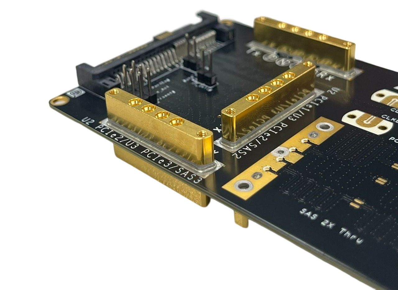
1. Strengthening of the Connector Structure
To improve the connector’s poor tolerance and decrease the probability of damage during use, Allion uses high-frequency connectors with bandwidth exceeding 40 GHz.
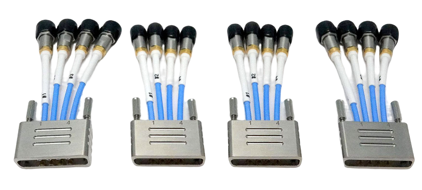
2. Modular Connectors and Cables
Allion’s set of modular integrated connection cables can be directly connected to related test equipment without additional cables, which greatly reduces the number of cables used during testing, as well as the frequency of plugging and unplugging. This means there is no need to purchase extra cables. Allion also prepares different lengths and connector types to meet usage demands.
Using fixtures developed by Allion gives you more flexibility and convenience. If you have product validation or customized measurement needs, please refer to the Allion Fixture Shopping Center or contact us at: service@allion.com
Technical Highlights